Dezhou Guanlu Precision Machinery Co.,Ltd

please visit our Youtube


Dezhou Guanlu Precision Machinery Co.,Ltd
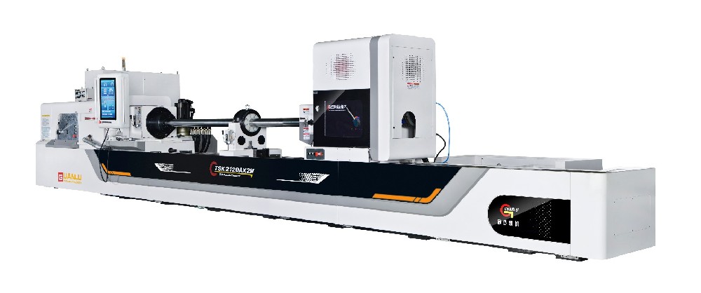
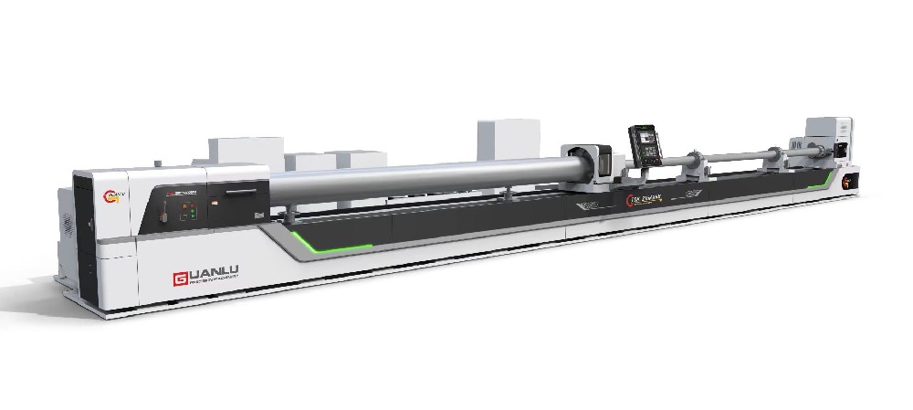
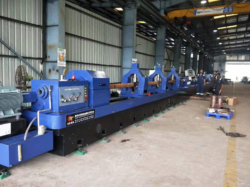
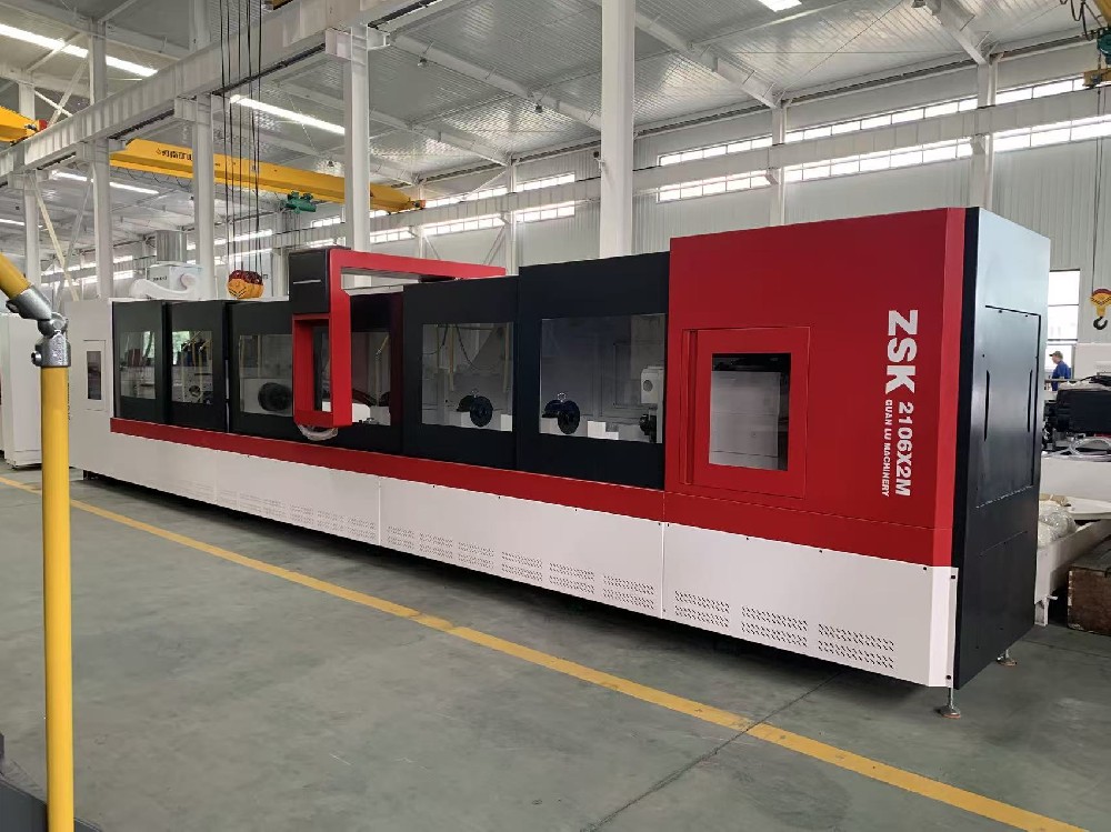
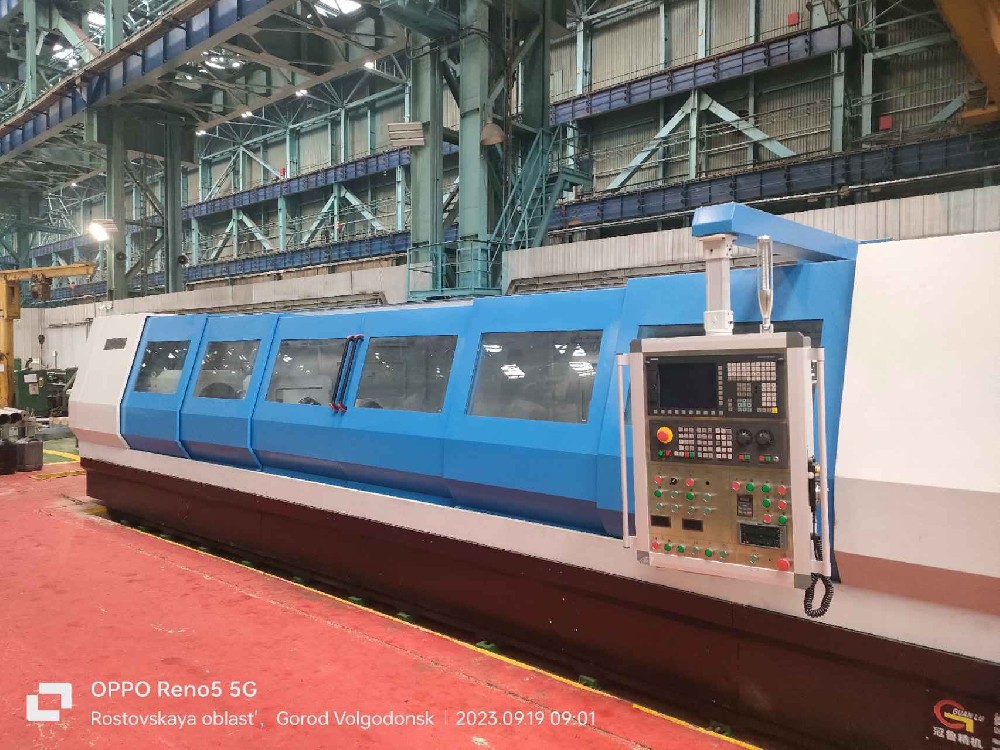
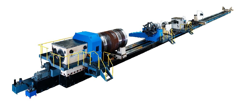
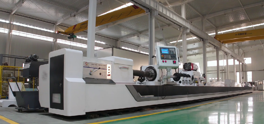
1. Machine Overview
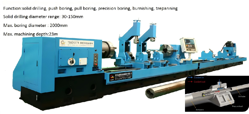
2.1 Machine processing scope
Drilling range: Φ30~ Φ100mm
Boring range: Φ40 ~ Φ200mm
Outer diameter range of workpiece: Φ60 ~ Φ400mm
2.2 Machine tool functions
Drilling and boring functions.
Drilling: BTA drilling mode, through the cutter arbor to the rear chip.
Boring: Push boring mode, through the bottom hole of the workpiece to the front chip.
2.3 Main structure of machine tool
2.3. 1 Main components of machine tools
Bed body, headstock, oil feeder, cutter arbor bracket, drill pipe box, sliding guide rail, pinion and rack, cooling system, control system, electric box, workpiece bracket, etc.
2.3. 2 Workpiece clamping
The manual three-jaw chuck on the headstock clamps one end of the workpiece, and the oiler cone automatically presses the other end of the workpiece.

Workpiece clamping diagram
1.3. 3 Machine tool control system
Control system: PLC
Z-axis: Longitudinal feed motion of drill pipe box, servo motor drives rack and pinion mechanism through deceleration mechanism.
X-axis: The oil feeder servo presses the workpiece, and the servo motor drives the pinion and rack mechanism through the deceleration mechanism.
1.3. 4 The basic parts such as box body, bed body and supporting plate are precision cast with high quality cast iron. After casting, they are aged twice to eliminate internal stress, stabilize structure and size, and improve mechanical properties.
1.3. 5 Bed body
The bed body is cast with resin sand, and normalizing treatment is carried out after casting. The bed body adopts a split structure, assembled together by high-strength bolts, and positioned by taper pins.
Adopt double rectangular sliding guide rail, precision grinding, high hardness of guide rail surface quenching.
The bed body is equipped with oblique rack, which is used for tool feed transmission. The rack has been precision machined and quenched. The machine tool has large load, sufficient rigidity and stable transmission.
V-shaped oblique ribs are arranged inside the bed body, which has high support strength and is not easy to deform; The outer wall of the bed directly supports the guide rail, which can withstand large cutting force. The rigidity of the guide rail is good, and it is not easy to deform and shake during processing, which is conducive to improving the processing quality and efficiency of the machine tool.
An oil return groove is cast around the bed body, and an oil shield is installed on the oil return groove, and the cutting oil on the bed body is automatically returned to the cooling oil tank.
1.3. 6 Headstock
It is used to drive the workpiece to rotate and is fixed at the left end of the bed body.
Manual 3-speed and stepless speed regulation within the gear, using a servo spindle motor to drive the spindle to rotate through the belt and gearbox, and assembling a manual three-jaw chuck at the front end of the headstock for clamping workpieces.
Precision grinding of gears; The gear tooth surface is quenched at high frequency, so that the gear can obtain high strength, high hardness, high wear resistance and high fatigue limit, and can withstand relatively large alternating load and impact load.
External lubricating oil tank for gears and bearings circulating lubrication, oil tank installation of low liquid level alarm device.
A button board is installed on the Headstock box, which has the functions of spindle point, feed forward, feed backward, and emergency stop.
1.3. 7 Oil Pressure head
Used for tool guide, tool oil supply, tool arbor support.
The servo motor is used to drive its axial movement, which is suitable for the processing of workpieces with different lengths, as well as tightening and loosening of workpieces. The servo motor can operate in torque mode or position mode.
The rotary bearing of the oil Pressure head is installed in the inner body of the oil Pressure head , with good rigidity and high rotary accuracy.
The rotary seal is installed on the outside of the right end of the Oil Pressure head body, which is convenient for maintenance.
The right end of the Oil Pressure head is equipped with a cutter arbor support sleeve for supporting the cutter arbor.
The left end of the Oil Pressure head is equipped with a guide sleeve, a cone disk, and an oil retaining device. The cone disk is used for positioning the workpiece, and the guide sleeve is used for guiding the tool.
The oil retaining device is a push-pull structure, and an oil receiving box is installed at the lower part of the oil retaining device to make the cutting oil flow back to the oil tank.
1.3. 8 Drill box
It is used to drive the tool to rotate and is installed on the feed support plate.
Manual 3-speed, stepless speed regulation in the gear, using the servo spindle motor to drive the spindle to rotate through the belt, pulley, and gear train.
The left end of the spindle is equipped with a tool shank connecting sleeve for clamping the tool.
The right end of the spindle is equipped with a chip removal bucket for discharging chips.
Precision grinding of gears; The gear tooth surface is quenched at high frequency, so that the gear can obtain high strength, high hardness, high wear resistance and high fatigue limit, and can withstand relatively large alternating load and impact load.
External lubricating oil tank for gears and bearings circulating lubrication, oil tank installation of low liquid level alarm device.
1.3. 9 Drill bar support
For supporting the drill bar ;
It adopts a high-rigidity integral structure, and a support sleeve is assembled on it, which can absorb the impact and vibration generated in the processing process.
Installation of automatic pull mechanism, the feed plate can automatically pull the arbor bracket back to the initial position when retracting the knife.
1.3. 10 Cooling system:
It is mainly composed of cooling pump, chip box, oil tank, etc., which provides enough cutting oil for deep hole processing.
Above ground fuel tank, the fuel tank is fully welded with high-quality steel plate.
A telescopic protective cover is installed between the chip boxes on the fuel tank to cover the fuel tank to prevent sundries from falling into the fuel tank.
The pressure, liquid level, oil temperature and flow rate of cutting oil can be displayed digitally on the control station.

Cooling system diagram
1.3. 11 Feed pallets
Used to drive the tool to move axially.
The automatic lubrication station is used to lubricate the sliding rail surface at fixed time and quantity.
A push button plate is installed on the supporting plate, which has the functions of punching the main shaft of the drill pipe box, feeding forward, feeding backward, and emergency stop.
1.3. 12 lubrication system
The sliding guide rail surface of the feed support plate adopts automatic lubrication station for timing and quantitative lubrication, and has the function of low liquid level alarm.
The bearings and gears of the headstock are lubricated by an independent external fuel tank with low liquid level alarm function.
Bearings and gears of drill pipe box are lubricated by an independent external oil tank with low liquid level alarm function.
The lubricator support plate and the cutter holder support plate are lubricated by manual lubrication pump.
1.3. 13 Workpiece brackets
Used for workpiece preposition.
The operator puts the workpiece on the workpiece bracket first, and after the workpiece is clamped and positioned, the workpiece leaves the bracket.
The V-frame on the workpiece bracket is manually raised and lowered using the T-screw.